Society of Naval Architects and Marine Engineers
Additional applications of the Vor-Prop may be found
in industrial pumps, irrigation systems and medical
devices. Comparative tests with various hydraulic
pump units are yet to be made.
Society of Naval Architects and Marine Engineers
Propeller & Shafting Conference 2023
sname .org Norfolk VA USA
Research of the Vortex Propulsor Concept
Richard Hayman (M), Ibrahim Mesinovic (V)*, Dijana Basta (V)* *
*Swedish Society of Marine Engineers
** Aeronautical Institute of Croatia
Abstract:
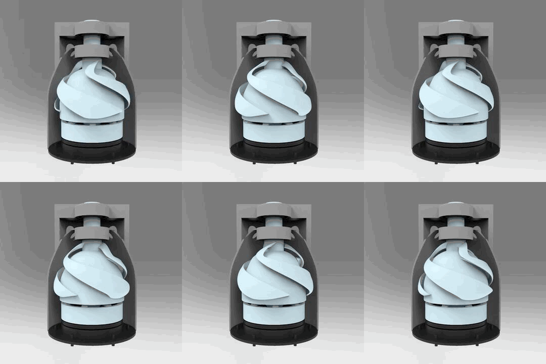
Recent research in the possible applications of the vortex propulsor – Vor-Prop – have included open cylinder model, a shafted coaming contained compact model and a double counter rotational internal turbine model. CFD analysis indicates efficiencies in applications including ship propulsion, UAV propulsion, industrial and agricultural pumping, and medical devices. Prototypes and testing have been pursued at MARIN, Netherlands, and Swedish laboratories.
RESEARCH MODELS:
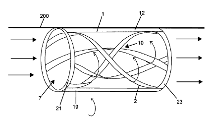
The principle of the vortex propulsor is to create pressure differentials by spinning helical foils arrays, with a low center vortex drawing water into the cylinder and providing flow thrust. This infers a large volume of water being drawn through the center passage. The effectiveness of this concept and its applications are still to be determined in various designs. The original hydraulic principle was developed by Alexander Gorlov for electrical generation captured by helix foil array in tidal and river flow sites.
WATER TURBINE GENERATION:
Helix hydrofoil blade array turbines are a proven technology as currently deployed in tidal & river flows. The advantage is in low flow generation versus comparable screw propeller water turbines.
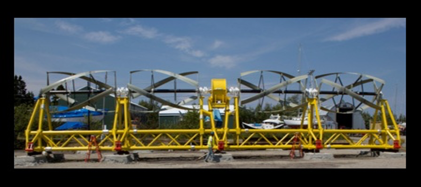
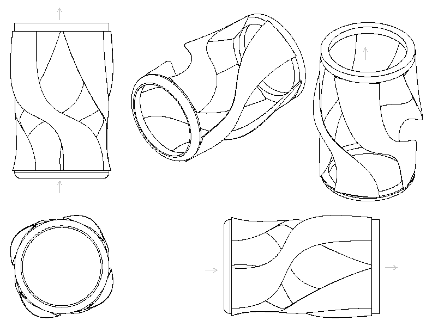
This installation, funded by the US Dept. of Energy is in the Coobscook Bay, Maine. Our subsequent research to turn this energy capture design into propulsion has indicated efficiencies leading to various models and testing. Whether the ‘tangential’ velocity can be used as ‘axial’ velocity is the crux of the investigation. The possible use of Vor-Prop for marine propulsion leads to shaft mounted versions for comparison to standard screw prop, Sharrow style and other evolved propeller designs. It may be unlikely that any Vor-Prop would be useful in high rpm high speed propulsion. There may be use in low rpm ‘service’ speed for vessels of various sizes. The patent document describes possible use of Vor-Props integrated in hulls as large cylindrical pumps to draw and expel large water volumes to supplement any aft propellers. A U.S. Patent #10,099,761 was issued in 2018 under the title “Water Turbine Propeller”. Patent drawings: Cylindrical: Patent drawings: Shaft Mount The name, Vor-Prop, has been registered as trademark and research sponsored by Vor-Prop LLC.
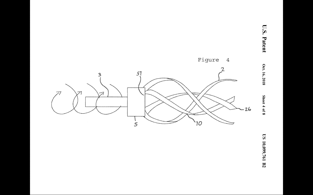
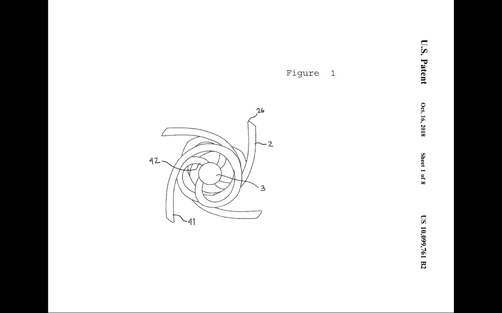
COMPUTER MODELS:
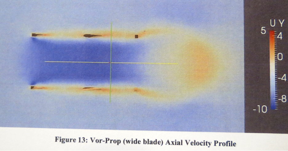
Simulations were realized by Joe Baroutey, Blake Koop and Matt Sinott of Computing Future Solutions using pressure isocontours and vorticity profiles on the open center cylindrical Vor-Prop.
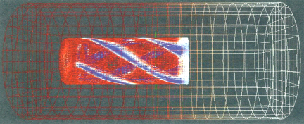
Computer hydro flow simulation and analysis:
Simulated Volume
600mm x 1020mm x
600mm
Blade Thickness
Blade Height
50.0 mm
12.5 mm
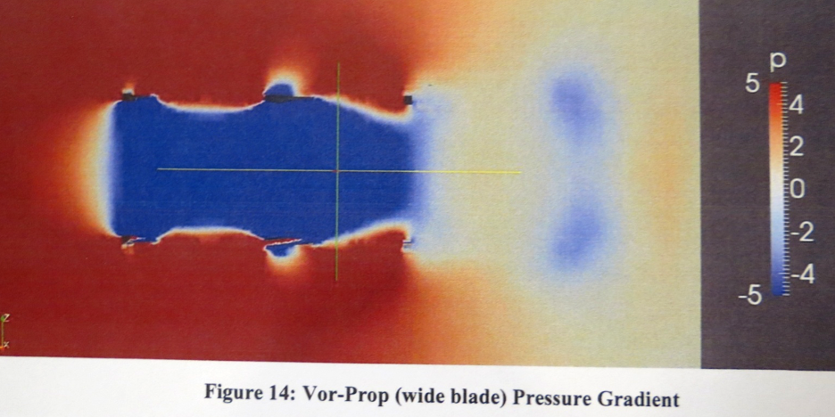
Initial pressure differentials:
SIMULATION SUMMARY:
Recommendations:
- Increasing the blade width added structure to the
flow pattern and focused the velocity profile. It may
be beneficial to simulate the wide blade model further,
as the pressure gradient looks as though it is still
developing. Widening the blade further and adding
those results to the comparison would be helpful as
well. - The velocity profile is a strong indicator of the
effectiveness of the Vor-Prop. Conservation of
momentum in this system requires that the forward
momentum of any marine vessel be equal and opposite
to the momentum of the water displaced by the Vor-
Prop. Focusing this velocity profile (and therefore
momentum) should be the goal when altering design
parameters. - Another strong indicator is the pressure difference
on the blades themselves. Notice in the high pressure
and low pressure regions on either side of the Vor-
Prop blades. This is a very direct visualization of the
net force which creates motion.
Mechanical linkage or electrical induction would
drive the Vor-Prop as per vessel design.
An air cushion or sealed oil bearing system for a
larger Vor-Prop rotating cylinder could mitigate
friction in the system.
INSTALLATION:
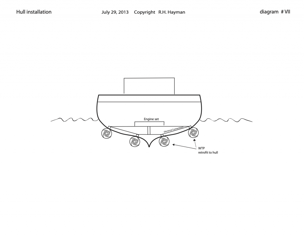
A larger Vor-Prop configuration could be built
integrated or attached to a vessel hull.
The Vor-Prop may be most effective at slow
speed and for large vessel propulsion with low rpm
diesel and electric engine applications. A moderate
engine speed will be matched by greater torque at a
lower relative rpm than existing screw propellers.
High rpm parameters will also be tested for small craft
installation.
If Vor-Prop rotation of 3 or 4 times hull speed
may match current speed levels and yield a significant
reduction in fuel costs, the design may develop into an
alternative marine propulsion system.
Questions of rudder placement or direction
reversibility are yet to be studied.
The general description of the Vor-Prop for patent
filings includes both hull integrated and fitted onto
standard propeller shafts. As ongoing research
follows the demonstrable effects of the design –
variables of size, number of foils blades, rotational
speed and flow dynamics – the optimization and
variations of the design will indicate its applications.
APPLICATIONS:
If this hydraulic principle is proven and utilize
the Vor-Prop may have applications in marine
propulsion in various sizes from small craft to large
ships. An installation integrated into hull construction
may be most effective.
The goal is a propulsor with low rpm moving
large water volumes with high torque, no cavitization
and a more efficient flow in the aft wash. The result
could be comparable to marine animal propulsion such
as squid, taking in large volumes of water to expel and
move forward. The greater the flow through, the more
efficient the propulsor would be. There would be an
optimum foil design, cylinder diameter and length
calculated to the application.
Manufacturing of the Vor-Prop may prove more
efficient as non-metal foils could be extruded and
assembled and installed as per the vessel requirements.
The size and length of cylinder and the number
and position of foil blades will be the determinate of
efficacy as prototypes will determine.
Small vessel engines could have fewer foil blades.
Larger versions for ships may realize more blades and
different power delivery attachment.
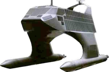
Application example: A swath hull design (smallwater area twin hull) could install the Vor-Prop intothe subsurface hulls with intake openings and smoothpropulsive flow from the ends.
Additional applications of the Vor-Prop may be found
in industrial pumps, irrigation systems and medical
devices. Comparative tests with various hydraulic
pump units are yet to be made.
BENEFITS:
The advantages of Vor-Prop for ocean
sustainability include greater fuel efficiency to reduce
pollution, reduction of noise and vibrations.