Society of Naval Architects and Marine Engineers
Propeller & Shafting Conference 2023
sname .org Norfolk VA USA
Research of the Vortex Propulsor Concept
Richard Hayman (M), Ibrahim Mesinovic (V)*, Dijana Basta (V)* *
*Swedish Society of Marine Engineers
** Aeronautical Institute of Croatia
Abstract:
Recent research in the possible applications of the vortex propulsor – Vor-Prop – have included open cylinder model, a shafted coaming contained compact model and a double counter rotational internal turbine model.CFD analysis indicates efficiencies in applications including ship propulsion, UAV propulsion, industrial and agricultural pumping, and medical devices. Prototypes and testing have been pursued at MARIN, Netherlands, and Swedish laboratories.
RESEARCH MODELS:
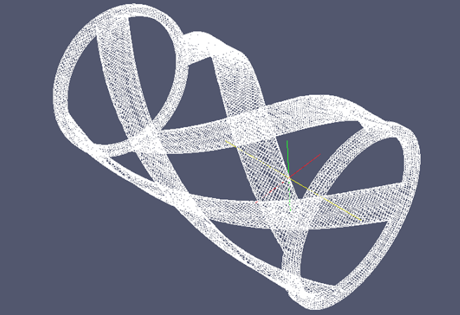
The principle of the vortex propulsor is to create pressure differentials by spinning helical foils arrays, with a low center vortex drawing water into the cylinder and providing flow thrust. This infers a large volume of water being drawn through the center passage. The effectiveness of this concept and its applications are still to be determined in various designs.
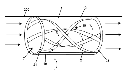
The original hydraulic principle was developed by Alexander Gorlov for electrical generation captured by helix foil array in tidal and river flow sites.
WATER TURBINE GENERATION:
Helix hydrofoil blade array turbines are a proven technology as currently deployed in tidal & river flows. The advantage is in low flow generation versus comparable screw propeller water turbines.
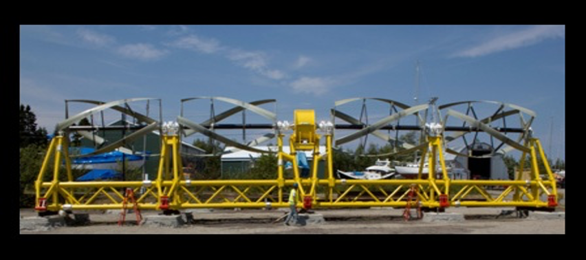
Our subsequent research to turn this energy capture design into propulsion has indicated efficiencies leading to various models and testing. Whether the ‘tangential’ velocity can be used as ‘axial’ velocity as described by William Wood, is the crux of the investigation.
The possible use of Vor-Prop for marine propulsion leads to shaft mounted versions for comparison to standard screw prop, Sharrow style and other evolved propeller designs. It may be unlikely that any Vor-Prop would be useful in high rpm high speed propulsion. There may be use in low rpm ‘service’ speed for vessels of various sizes.
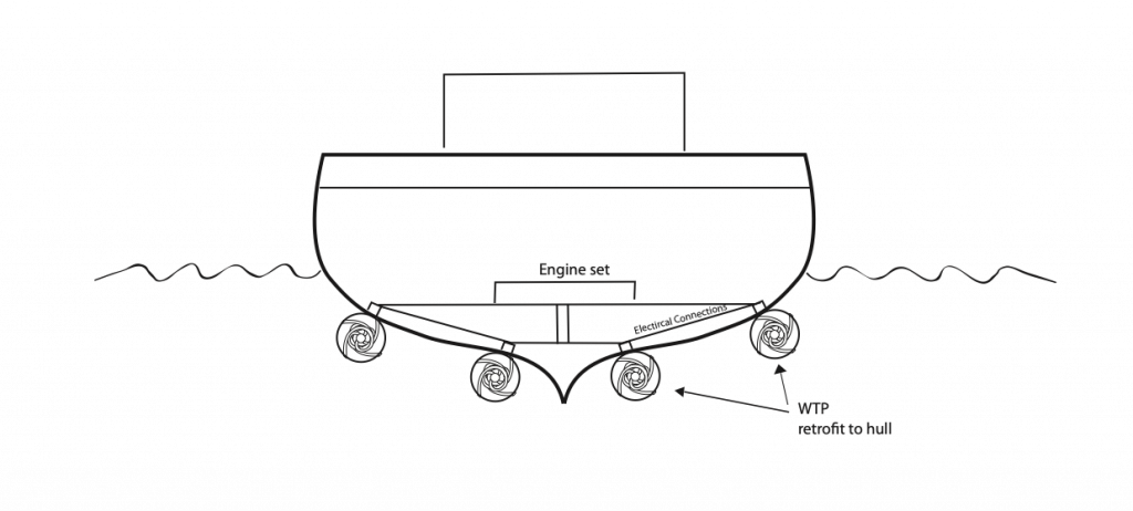
The patent document describes possible use of Vor-Props intergrated in hulls as large cylindrical pumps to draw and expel large water volumes to supplement any aft propellers.
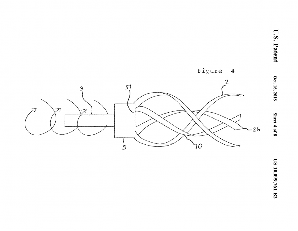
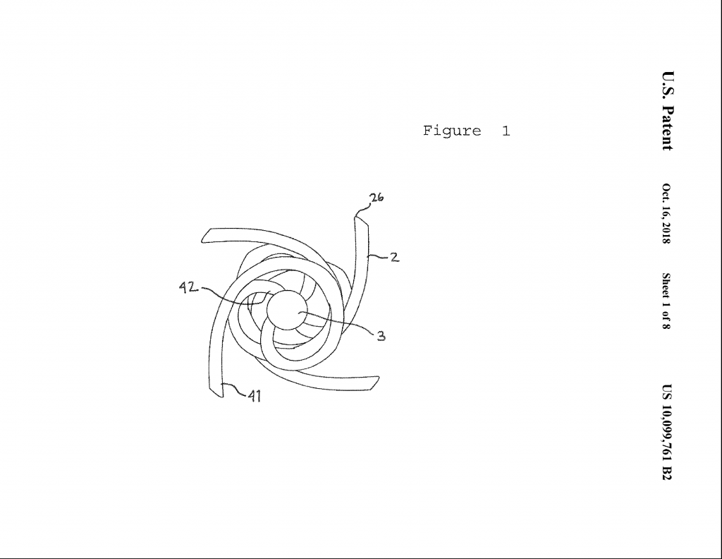
A U.S. Patent #10,099,761 was issued in 2018 under the title “Water Turbine Propeller”.
The name Vor-Prop has been registered as trademark.
COMPUTER MODELS:
Simulations were realized by Joe Baroutey, Blake Koop and Matt Sinott of Computing Future Solutions using pressure isocontours and vorticity profiles on the open center cylindrical Vor-Prop.
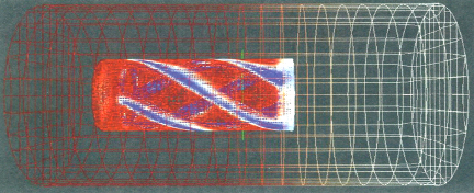
Simulated Volume 600mm x 1020mm x 600mm
Blade Thickness 50.0mm
Blade Height 12.5mm
Initial pressure differentials
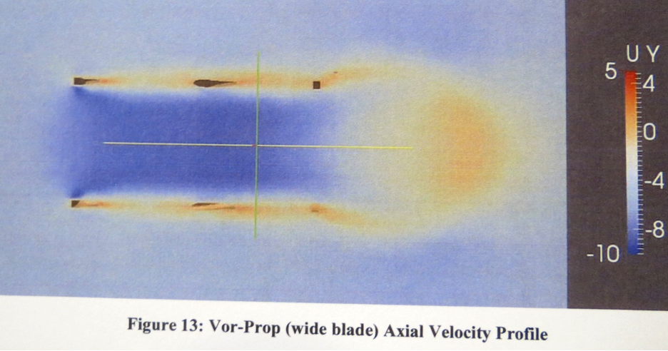
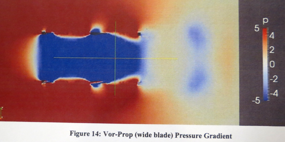
This indicates continuous flow pressure effect.
SIMULATION SUMMARY:
Recommendations:
- Increasing the blade width added structure to the flow pattern and focused the velocity profile. It may be beneficial to simulate the wide blade model further, as the pressure gradient (Figure 6) looks as though it is still developing. Widening the blade further and adding those results to the comparison
would be helpful as well.
- The velocity profile is a strong indicator of the effectiveness of the Vor-Prop.
Conservation of momentum in this system requires that the forward momentum of any marine vessel be equal and opposite to the momentum of the water displaced by the Vor-Prop. Focusing this velocity profile (and therefore momentum) should be the
goal when altering design parameters. - Another strong indicator is the pressure difference on the blades themselves.
Notice in (Figure 7) the high pressure and low pressure regions on either side of the Vor-Prop
blades. This is a very direct visualization of the net force which creates motion. Prototype testing is underway to realize this effect.
APPLICATIONS:
If this hydraulic principle is proven and utilized, the Vor-Prop may have applications in marine propulsion in various sizes from small craft to large ships. An installation integrated into hull construction may be most effective.
The goal is a propulsor with low rpm moving large water volumes with high torque, no cavitization and a more efficient flow in the aft wash. The result could be comparable to marine animal propulsion such as
squid, taking in large volumes of water to expel and move forward. The greater the flow through, the more efficient the propulsor would be. There would be an optimum foil design, cylinder diameter and length calculated to the application.
Manufacturing of the Vor-Prop may prove more efficient as non-metal foils could be extruded and assembled and installed as per the vessel requirements.
The size and length of cylinder and the number and position of foil blades will be the determinate of efficacy as prototypes will determine.
Small vessel engines could have fewer foil blades. Larger versions for ships may realize more blades and different power delivery attachment.
Mechanical linkage or electrical induction would drive the Vor-Prop as per vessel design.
An air cushion or sealed oil bearing system for a larger Vor-Prop rotating cylinder could mitigate friction in the system.
INSTALLATION:
A larger Vor-Prop configuration could be built integrated or attached to a vessel hull.
The Vor-Prop may be most effective at slow speed and for large vessel propulsion with low rpm diesel and electric engine applications. A moderate engine speed will be matched by greater torque at a lower relative rpm than existing screw propellers. High rpm parameters will also be tested for small craft installation.
If Vor-Prop rotation of 3 or 4 times hull speed can match current speed levels and yield a significant reduction in fuel costs, the design may develop into an alternative marine propulsion system.
Questions of rudder placement or direction reversibility are yet to be studied.
The general description of the Vor-Prop for patent filings includes both hull integrated and fitted onto standard propeller shafts. As ongoing research follows the demonstrable effects of the design – variables of size, number of foils blades, rotational speed and flow dynamics – the optimization and variations of the design will indicate its applications.
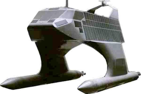
Application example: A swath hull design (small water area twin hull) could install the Vor-Prop into the subsurface hulls with intake openings and smooth propulsive flow from the ends.
Additional applications of the Vor-Prop may be found in industrial pumps, irrigation systems and medical devices. Comparative tests with various hydraulic pump units are yet to be made.
BENEFITS:
The advantages of Vor-Prop for ocean sustainability include greater fuel efficiency to reduce
pollution, reduction of noise and vibrations.
ENVIRONMENTAL:
Vor-Prop would be less injurious to marine life than faster churning screw propellers. It would also reduce ‘prop chop’ of marine life as the helix would create its own exterior buffer pressure, as has been demonstrated in Gorlov generators. Any life drawn into the flow would be turned about and sent through.
PROTOTYPE TEST MODELS
These are the recent prototype test models:
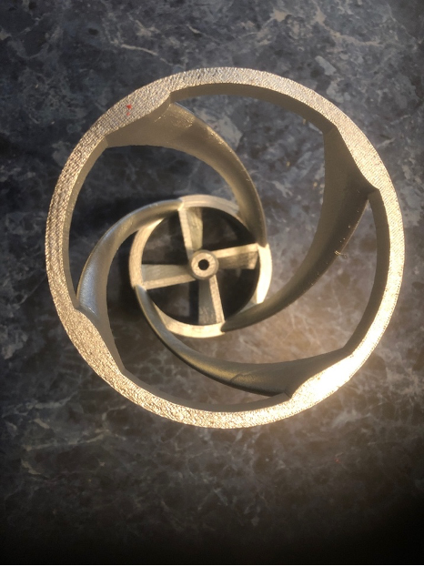
This model was cast in bronze per the specifications of the test equipment at MARIN. The aim was to measure any effect of the helical foils. For shaft mounting, a ring with blade struts was added to the cylinder array.
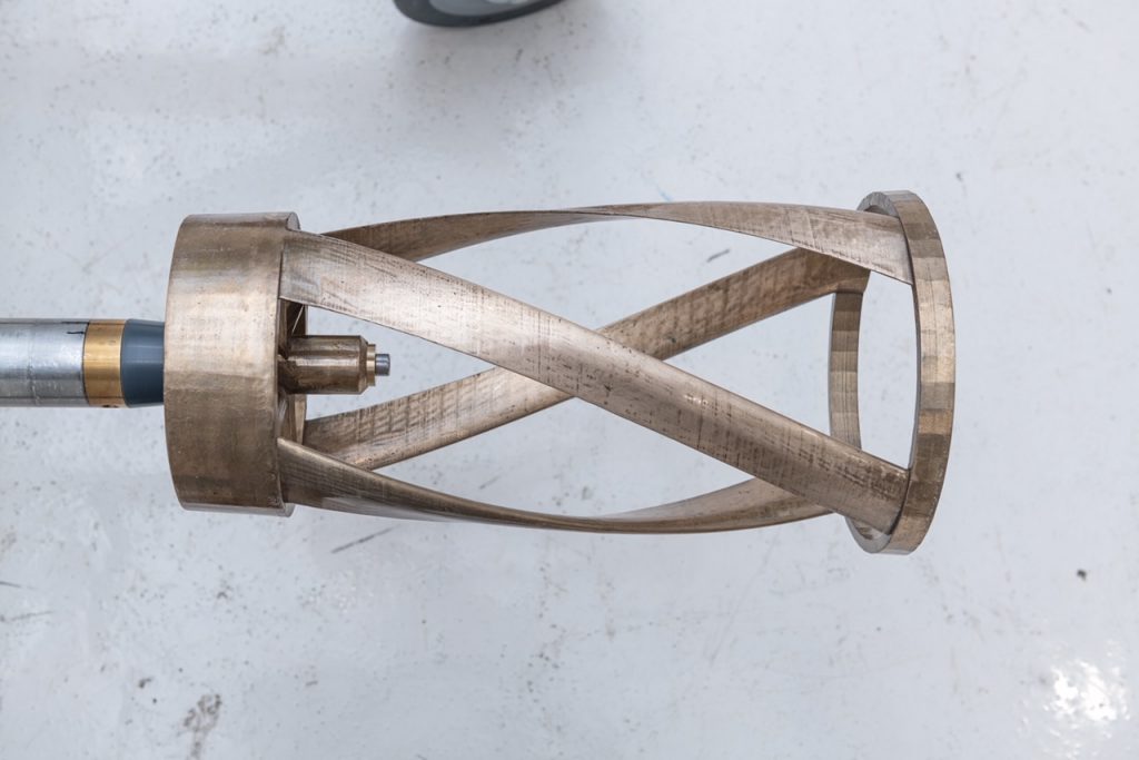
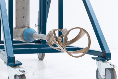
This model would have had a fraction of the weight had it been made from aviation ABS or aluminum. The MARIN laboratory did not accept these materials as unstable for testing.
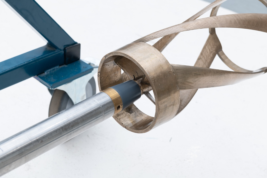
Due to the extended weight of the helical array, the model produced imbalanced motion vibrations and stressed the sensors imbedded in the mounting. Proposed rpm of 1500 was stopped at 700 rpm due to this vibration.
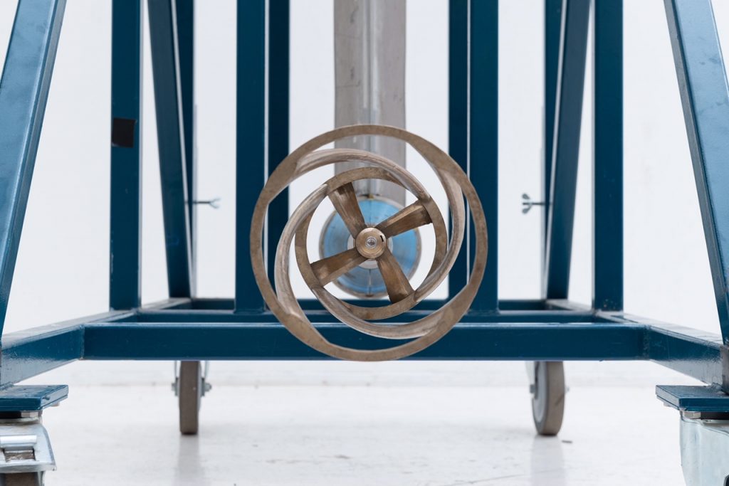
No data from the foils array was gathered. Propulsion was measured in the whole unit, but undifferentiated from the impeller mounting designed to hold the foil array. MARIN was unable to measure the cylindrical array as an open unit.
The thrust data generated showed no advantage versus comparable screw propeller. This effort was inconclusive, as this design model is a hybrid of shafted designs and the open cylinder design.
We have yet to identify a test lab that has the facilities to tank test the cylindrical model.
A full report by MARIN of this research is attached.
DIJANA BASTA Model
This is small size shaft mounted prototype designed by Dijana Basta:
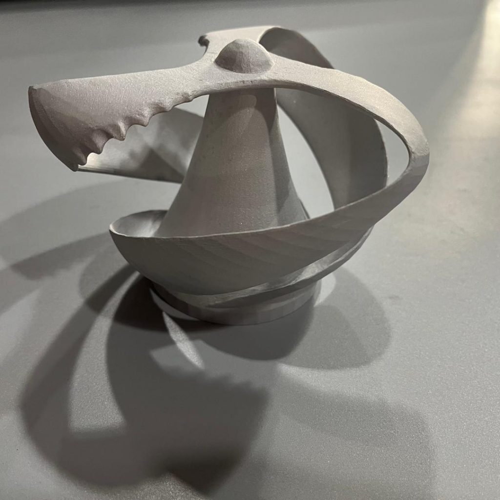
This Vor-Prop model has been printed in aluminum with 6 cm radial width, 7.5 cm depth on shaft fitting is being tested.
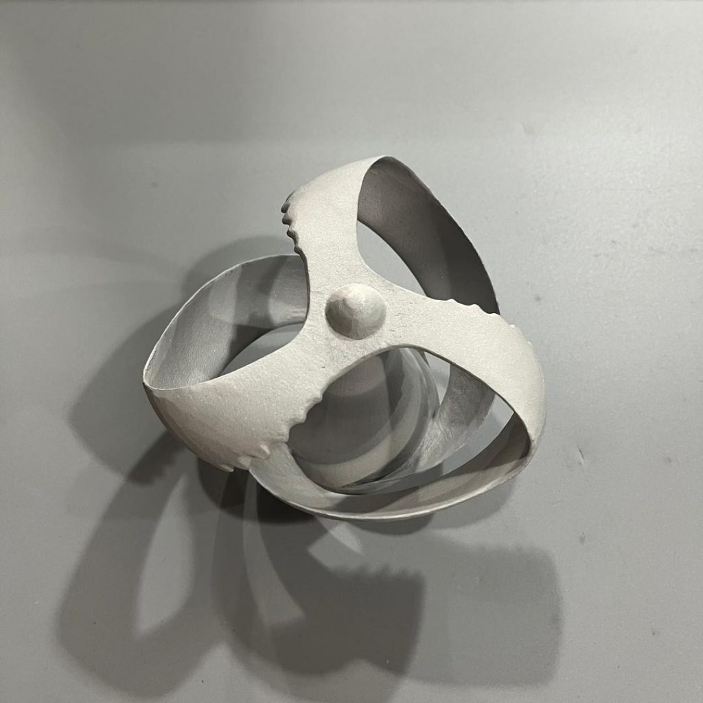
This model may prove effective for alternative to small propellers. Tank tests are yet to be performed.
Ibrahim Mesinovic Models
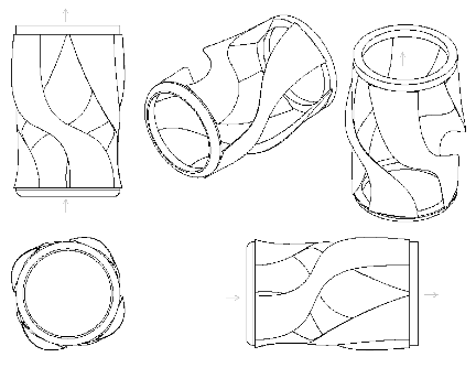
Vor-Prop virtual models as designed by Ibrahim Mesinovic:
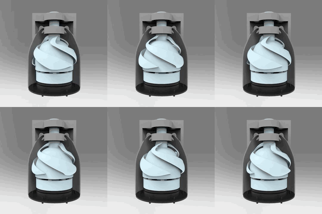
This prototype is contained in a coaming structure which directs and boosts the pressure differentials of the Vor-Prop, is yet to be built and tested.
THRUSTER MODEL
Another proposed use of the Vor-Prop is as thruster driver, installed in ships or other pumping applications:
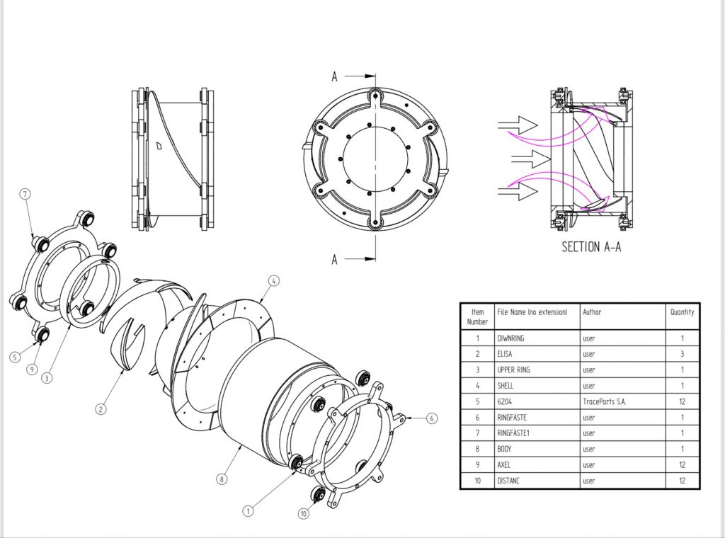
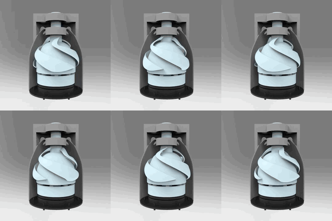
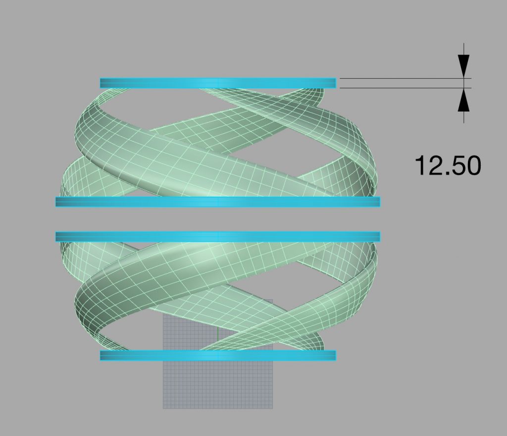
A double Vor-Prop combines two semi-spherical helical foil blade arrays rotated in opposite directions:
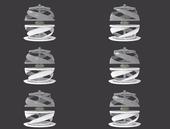
This model has been tested as propulsor for an autonomous underwater vessel with pressure generated to supply outlet water jets with high pressure water volume for maneuvering.
Each array is driven by power application from top and bottom connectors creating pressure differential with a low pressure vortex drawing water in from above and below, expelling at the horizontal center into hydraulic gates controlled for variable propulsion.
Variable speeds applied to each Vor-Prop array may alter the internal pressures for changing control and directionality, directing propulsion in sub-sea applications. Greater efficiency may be realized compared to external screw propellers or water jet pump outlets.
The resultant maneuverability of the UAV with this double Vor-Prop sphere. The design is under prototype modeling and testing in Sweden.
These various efforts have been more indicative than conclusive. More designs and tests are required to realize possible applications of the Vor-Prop concept.
PROJECT GOALS:
• Research hydraulic principle of vortex driven thrust
• Provide comparables to screw propeller technology
• Enable new vessel hull integrated propulsion
• Reduce fuel consumption and pollution
• Reduce aquatic noise and vessel vibration
• Test other applications of vortex propulsion for use in other industries that move liquids via pumps and water diversion systems.
• QUESTIONS FOR VOR-PROP:
1: Is this “better” than traditional means, i.e. efficiency, or is it giving designers an alternate set of constraints to balance against in a given design?
• Vor-Prop will induce a flow through effect that will be less turbulent than a screw propeller, the greater the flow, the more thrust. This may be more efficient by a factor that would make significant saving in fuel costs.
• 2: Is there some type of economy of scale by lining these up end to end, perhaps adjusting the pitch of the latter sections?
• We propose the Vor-Prop be integrated in hull construction to utilize the longest length possible for better performance. The size and pitch of the hydro-blades is key to the impelling of flow and thrust. The blades may also be flexible and adjustable as are some screw propellers and turbines.
• 3: Is this meant to be enclosed or exposed? If enclosed, would it help to restrict the end a little bit to optimize thrust, as is a rocket nozzle?
• Cylindrical casing will be tested once the hydraulic principles are better defined. The cowling around screw propellers (Kort nozzles, etc) focuses flow for use in steerable props at the cost of more friction of water flow. Vor-Prop may be produced in different models, some for major ships, others small for bass fisher size electric outboard motors, and various other applications.
• 5: What is the difference in performance between compressible atmosphere – air – versus fluids?
• Water is 800 times the density of air and not compressible after dissolved gases are expelled. This is the cause of cavitization as high pressure gas eats away at screw propeller blades as they bite the water flow at tip pressures. Vor-Prop will distribute this pressure along the helix blades. We do not know the effect of Vor-Prop at higher rpm. Our simulations have been at 1500 rpm, in the standard range for small craft propellers. The very large props on large ships have lower rpm, which we believe may be matched with very long Vor-Props for more efficiency. Very high speeds for racing boats may not be feasible. Advanced tank tests will indicate limitations or adaptions for specific applications.
• 6: Rather than constraining your design by mechanical linkages, have you considered electric drive? You would have so fewer moving parts, and direct control.
• We have renderings for shaft mountings to retrofit existing vessels, but better performance may occur with electrical induction drive instead of mechanical linkages. There may be different means to drive the Vor-Prop depending on the design of vessel as per purpose.
• 7: Have you considered smaller sizes, perhaps things that could be 3D printed? If you made one an inch in diameter, how well would it work?
• We have made the 60 cm long metal model as seen on the video for visualization and initial water tests. Most propeller research testing is done at a smaller scale for initial data measurement, then scaled up to application. Our 3D printer specialist is planning a carbon fiber print with titanium coating to provide more rigidity for water testing. Micro or macro scale Vor-Props may have different configurations – number of blades, length, diameter, etc. There may be applications in medical, agricultural and other industries as the research continues.
Answer to Reviewer Chad Oldfield:
Thank You for your consideration and analysing of our Vor-Prop concept.
As we develop this project, it is likely to have balance and vibrations issues.
Also, the CFD analyses that we have made are made just for blades, without calculating whole turbine as a one working part. We do not have final design and calculations. We have initial numbers for our unspecific type of turbine blades.
In our Vor-Prop design we follow natural shapes combined with research of Victor Schauberger. We believe that our improvement of some specific shapes will result with better performances than we have today in other types of blades.
(Fig 15 Vortex sketch)
To overcome recent issues with prototypes, we will use egg shape cone tip for the blade mount structure. The pressure differences between the lower-pressure region behind the cone and the higher-pressure region surrounding it should be sufficient to create a net force for propulsion. Careful design and optimization of the system will be necessary to achieve this effect.
Achieving a stable and controllable vortex behind the cone is crucial for harnessing its benefits for propulsion. The shape and size of the cone, as well as the turbine’s characteristics, will influence the vortex formation and fluid dynamics.
The turbine blades’ design will be optimized to capture the impulsion effect caused by pressure mediation in front of the cone. The blade shape, angle, and orientation will impact the efficiency of the propulsion system. We have already proven in CFD analyzes that blades have much better characteristics if they are covered with a relief like fish scales which induce micro eddies and add to the propulsive effect.
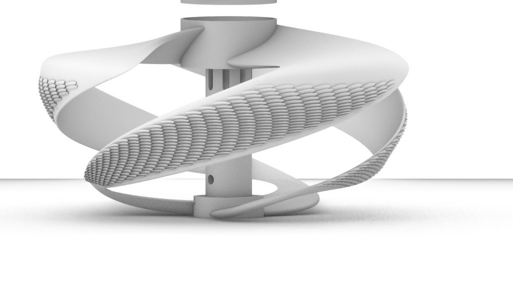
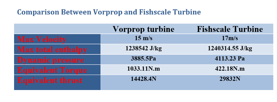
By combining a single cone design with fish scales on the blades and leveraging the insights gained from the CFD analysis and physical testing, we have the potential to create an efficient and
eco-friendly propulsion solution that could benefit the marine industry.
Dijana Basta
Answer to Reviewer William Wood:
You rightly identified the crux of our research, to create axial velocity from a structure that has been developed to capture tangential velocity in the helix water turbine. Vortex forces and hydro foil hydraulics have many vectors, some as interference, others as useful dynamic effects. We have identified pressure differentials that indicate potential propulsive effects in simulation of the cylindrical model, and when confined in the coaming contained model and double Vor-Prop turbine models.
The shafted models are inherently problematic due to flow interference of the mounting impeding the development of vortex induced pressures. These models have not yet been fully measured in tank tests. The prototype cast for MARIN proved unfeasible due to its extended form, weight and vibrations. What does not work may lead to designs that do work in specified applications. We will continue our research to optimize the forms that realize our hydraulic concepts.
Richard Hayman
DEVELOPMENT TEAM:
Richard Hayman, Capt.USMM,
Member, SNAME
Ibrahim Mesinovic, marine engineer and inventor, Sweden
Dijana Basta, aeronautical engineer and materials specialist, Croatia
Bil Becker, Aerotecture International, Inc., Chicago
Inventor and designer of helix wind turbines
John Sellers, inventor and engineer, designer of turbine generator control systems, magnetic propulsion for Royal Navy submarines
Joe Beyroutey, Blake Koop, Matt Sinnott,
Computing Future Solutions, Bethlehem, PA
Allen Rubenstein, Jason Wachler, patent attorney, Gottlieb, Rackman, Reisman, P.C. New York
Thank you for your interest and recommendations.